While researching some crazy bit of something, I stumbled on this description and drawing of Silcock and Lowe’s Patent Planes from the 1844 edition of Mechanics’ Magazine in England.
I read it. Then I read it again. Indeed. They are describing a laminated plane with an adjustable mouth. You adjust the mouth by loosening some screws and moving the rear part of the plane’s body, which rides in grooves in the sidewalls.
I can’t think of another reference to this sort of laminated bench plane that is this early. Check it out.
— Christopher Schwarz
The fourth instrument is a trying plane, suitable for both rough and fine work, and constructed in manner following:—
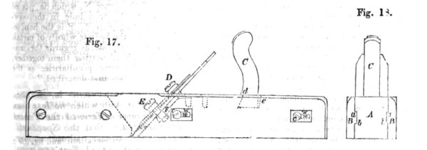
“Figure 17 is a side elevation of this plane, and figure 18 an end view. Instead of being formed of one piece of wood, as usual, it is composed of four or more separate pieces peculiarly combined together. The part A, which forms the centre, or heart of the plane (lengthwise), is made out of a piece of beech with the grain of the wood running crosswise, as usual. The proper place for the bed and mouth of the plane having been determined, these are cut out, and the two pieces into which the piece of wood is thus separated, are connected together by two side pieces, B B, also of beech, or of any other suitable sort of wood, placed with the fibre running longitudinally and tennoned to the central part A, by means of the tongues and grooves, a b. The tongues and grooves should fit closely the one into the other, particularly at top and bottom. The side pieces, B B, are attached permanently to the forepart of A, either by means of screws, as represented in the engravings, or by glueing, or by both screws and glue. At the back part the sides are secured by screws, c c, to the inside piece A in such manner that they may be shifted occasionally. W W, are two oblong metal washers, with oblong slots, w to, in them, which are let into the side pieces, B B, to such a depth, that when the screws, c e, are passed through the slots into the wood, their heads shall be below the surface of the wood. As the sole of the plane becomes worn down by use, and the mouth becomes consequently wider, by slackening or undoing the screws, the back part of the body A can be pushed forward and readjusted, so as to keep the mouth of the plane always of the best working width. The plane iron and its cover are united to each other by means of a nut and screw D, the nut being inserted in a bevelled-sided slot, so as to be nearly flush with the back of the iron; and thus united they are secured to the body of the plane by means of a screw, E (instead of by wedges, as usual), which is passed through the irons into a metal seat F, let into the back part of the centre piece A. C is the handle, which is made like the other handles before described with the grain of the wood at right angles to the length of the plane, and let into and secured in the wood in the manner represented by the dotted lines in figure 17. At the front it is cut away, so as to leave a shoulder, d, which rests upon the top of the centre piece A, and at the back there is a sufficient space left to allow of the insertion of a wedge e, by driving in which, the handle is firmly secured in its place.